




Friday, March 15, 2013
Sunday, January 27, 2013
Electronics & Communication Engineering Interview questions With Answers (Part-I)
Electronics & Communication Engineering
Interview questions With Answers Exclusive
on Ultimate EC
http://snk.to/f-cu3wdf5k only 170 kb
(Link Updated)

Sunday, August 19, 2012
Quck Heal TS 2011 10000% workiing Crack by MahammadVasim Khatri Ultimate EC
THIS POST IS WILDCARD ENTRY FOR THIS BLOG
[password: Comment Below and Add as Friend http://www.facebook.com/mahammadvasim.khatri]
I MahammadVasim Khatri(Wangdu) has developed this software to To fix "Some DLLs ARE MISSING" after Cracking Quick Heal TS 2011 (x86)
To use it Just Run File Quick Heal DLL FIXER.exe As Admin
Quick Heal Total Security 2011 Crack for 32bit(x86)
Problems Solved
1)Online Registration
2)Automatic Updates
3)PC Tuner Running
4)Fix Some Dll are Missing after Restart
::Procedure::
1) INSTALL QUICK HEAL TOTAL SECURITY 2011 TRIAL VERSION.
2) Exclude The Folder in Quick Heal (Not to get Delete the files)
How to do Second Step :
Run quick heal. Go To Files & Folders Section.
Select Exclude Files & Folders.
Click on Add button.
Add the quick heal folder and subfolders to the exclusion list.
Click on Save Changes button.
3) START COMPUTER IN SAFE MODE(Pressing F8 at boot menu).
4) COPY ALL THREE FILES FROM "Total Security" FOLDER AND PAST THEM INTO
(C:\Program Files\Quick Heal\Quick Heal Total Security) AND REPLACE OLDER ONES.
A)INFORI.dll
B)SCANABT.dll
C)SCANNER.exe
D)Scanres.dll
5) NOW COPY THE FILE PRESENT IN THE "PC Tuner" INTO
(C:\Program Files\Quick Heal\Quick Heal Total Security\PCTUNER) AND REPLACE OLDER ONES.
E)PCTRES.dll
6) START PC IN NORMAL MODE.
7) Update Quick Heal
8) Disable Quick Heal Self Protection [Most Immportant]
Run quick heal.
Go to Settings
Click on Self Protection (Confirm that it is OFF)
9) Now Open Quick Heal DLL FIXER.exe [password:ask at http://www.facebook.com/mahammadvasim.khatri]
10) You Have to Run Quick Heal DLL FIXER.exe after each Update (Otherwise you will get error "Some Dlls Files are Missing")
QHTS 2011 FOR UNLIMITED PERIOD
UNLIMITED AUTOUPDATES
PCTUNER
File Download:
Click Here
http://www.mediafire.com/?kuqp1y46lksz1qz
if you find my website useful and helpful for you
please support my site to keep my website online ,
::::::::::::>>>>>>www.ultimateec.blogspot.com<<<<<<:::::::::::::
All Copyrights To Ultimate Electronics & Communication @ 2012
[password: Comment Below and Add as Friend http://www.facebook.com/mahammadvasim.khatri]
I MahammadVasim Khatri(Wangdu) has developed this software to To fix "Some DLLs ARE MISSING" after Cracking Quick Heal TS 2011 (x86)
To use it Just Run File Quick Heal DLL FIXER.exe As Admin
Quick Heal Total Security 2011 Crack for 32bit(x86)
Problems Solved
1)Online Registration
2)Automatic Updates
3)PC Tuner Running
4)Fix Some Dll are Missing after Restart
::Procedure::
1) INSTALL QUICK HEAL TOTAL SECURITY 2011 TRIAL VERSION.
2) Exclude The Folder in Quick Heal (Not to get Delete the files)
How to do Second Step :
Run quick heal. Go To Files & Folders Section.
Select Exclude Files & Folders.
Click on Add button.
Add the quick heal folder and subfolders to the exclusion list.
Click on Save Changes button.
3) START COMPUTER IN SAFE MODE(Pressing F8 at boot menu).
4) COPY ALL THREE FILES FROM "Total Security" FOLDER AND PAST THEM INTO
(C:\Program Files\Quick Heal\Quick Heal Total Security) AND REPLACE OLDER ONES.
A)INFORI.dll
B)SCANABT.dll
C)SCANNER.exe
D)Scanres.dll
5) NOW COPY THE FILE PRESENT IN THE "PC Tuner" INTO
(C:\Program Files\Quick Heal\Quick Heal Total Security\PCTUNER) AND REPLACE OLDER ONES.
E)PCTRES.dll
6) START PC IN NORMAL MODE.
7) Update Quick Heal
8) Disable Quick Heal Self Protection [Most Immportant]
Run quick heal.
Go to Settings
Click on Self Protection (Confirm that it is OFF)
9) Now Open Quick Heal DLL FIXER.exe [password:ask at http://www.facebook.com/mahammadvasim.khatri]
10) You Have to Run Quick Heal DLL FIXER.exe after each Update (Otherwise you will get error "Some Dlls Files are Missing")
QHTS 2011 FOR UNLIMITED PERIOD
UNLIMITED AUTOUPDATES
PCTUNER
File Download:
Click Here
http://www.mediafire.com/?kuqp1y46lksz1qz
if you find my website useful and helpful for you
please support my site to keep my website online ,
::::::::::::>>>>>>www.ultimateec.blogspot.com<<<<<<:::::::::::::
All Copyrights To Ultimate Electronics & Communication @ 2012
Sunday, August 5, 2012
Cellphone-Based Device Control With Voice Acknowledgement

Cellphone-Based Device Control With Voice Acknowledgement
Govani Hardik
Here is a circuit that lets you operate your home appliances like lights and water pump from your office or any other remote place. So if you forgot to switch off the lights or other appliances while going out, it helps you to turn off the appliance with your cellphone. Your cellphone works as the remote control for your home appliances. You can control the desired appliance by pressing the corresponding key. The system also gives you voice acknowledgement of the appliance status.
Circuit description
Fig.1 shows the circuit for cellphone based device control with voice acknowledgement. It comprises microcontroller AT89C51, DTMF decoder MT8870, voice recording/playback device APR9600 and a few discrete components.

Microcontroller AT89C51 is at the heart of the circuit. It is a low-power, high-performance, 8-bit microcontroller with 4 kB of flash programmable and erasable read-only memory (PEROM) used as on-chip program memory, 128 bytes of RAM used as internal data memory, 32 individually programmable input/output (I/O) lines divided into four 8-bit ports, two 16-bit programmable timers/counters, a five-vector two-level interrupt architecture, on-chip oscillator and clock circuitry. A 11.0592MHz crystal (XTAL1) is used to provide basic clock frequency for the microcontroller. Capacitor C3 and resistor R3 form the power-on reset circuit, while push-to-on switch S20 is used for manual reset.
Port pins P1.0 through P1.7 of the microcontroller are configured to get the input from push-to-on switches S1 through S8. Pins of Port P1 are pulled high via resistor network RNW1. Port pins P2.0 through P2.4 are configured to receive the decoded DTMF signal from DTMF receiver MT8870. The functions of the corresponding switches (S1 through S8) and cellphone keys are shown in Table I.

The DTMF decoder is used for decoding the mobile signal. It gets DTMF tone from the mobile headset’s speaker pins and decodes it into 4-bit digital signal. The DTMF decoder is operated with a 3.579MHz crystal (XTAL2 ) In DTMF receiver MT8870 (IC3), capacitor C12 is used to filter the noise and resistors R6 and R7 help to amplify the input signal using the internal amplifier.
Pin 16 of IC3 connected to resistor R5 provides the early steering output. It goes high immediately when the digital algorithm detects a valid tone pair (signal condition). Any momentary loss of signal condition causes ESt to return to low state.
Pin 17 of IC3 connected to capacitor C11 is bidirectional, acting as steering input/guard time output (St/GT). A steering logic VTStdetected at St causes the device to register the detected tone pair. The guard time output resets the external steering time constant, and its state is a function of ESt and the voltage at St.
Port P3 pins P3.6 and P3.7 of IC1 are configured to select the control source for the devices. These are connected to DIP switches S17 and S18 and pulled high via resistors R2 and R1, respectively. Here, we are using two control sources, switches and mobile’s key. DIP switches S17 and S18 select the control sources as shown in Table II.

Pin 2.5 of Port P2 is configured to show the rest status. That is, if none of the control sources is selected by DIP switches S17 and S18, LED1 glows. Resistor R14 limits the current through LED1.
Voice acknowledgement is provided by the APR9600 (IC2). It is a single-chip voice recording and playback device that can record and play multiple messages at random or in sequential mode for 60 seconds. The user can select sample rates with corresponding quality recording lengths. Microphone amplifier, automatic gain control (AGC) circuits, internal anti aliasing filter, internal output amplifier and message management are some of the features of the APR9600.
Here the APR9600 is configured in random-access mode, which supports two, four and eight messages of fixed durations. The length of each message is the total recording length available divided by the total number of memory segments/tracks enabled.
Audio processor APR9600 can store up to eight voice messages. Port P0 pins and P2.7 are configured to communicate with IC2. Port P0 pins trigger selection of the message. Port pin P2.7 is the input signal to identify whether the voice message is playing or not.

Fig.2: Pin configuration
of mobile headset
Pins P3.0 through P3.5 of Port P3 control the devices with the help of relays RL1 through RL6 via relay driver IC4.
A speaker is connected to IC2 for audio output. The speaker output drives the mic input of the mobile for audio acknowledgement. An electret microphone MIC1 is connected to IC2 to record the voice in IC2. LED2 flashes to show the busy status of IC2 during recording and playback. The audio messages to be recorded in APR9600, by using trigger switches S9 through S16, are shown in Table III. SPST switch S19 is closed for recording and switch S19 is opened for playback.

Fig.3 shows the power supply circuit. The 230V AC mains is stepped down by transformer X1 to deliver the secondary output of 9V, 500 mA. The transformer output is rectified by a full-wave bridge rectifier comprising diodes D1 through D4, filtered by capacitor C16 and then regulated by IC 7806 (IC5). Capacitor C15 bypasses the ripples present in the regulated 6V power supply. LED3 acts as a power-on indicator and resistor R16 limits the current through LED3.

Fig.3: Power supply circuit
An actual-size, single-side PCB for cellphone-based device control with voice acknowledgement is shown in Fig.4(View as PDF) and its component layout in Fig.5(View as PDF).
Recording and playback
For playback of any device status, open SPST switch S19 and press the corresponding switch (S9 through S16). The recorded audio can be heard from the speaker connected to pins 14 and 15 of IC2. Fig.2 shows the pin configuration of mobile headset.
Circuit description
Fig.1 shows the circuit for cellphone based device control with voice acknowledgement. It comprises microcontroller AT89C51, DTMF decoder MT8870, voice recording/playback device APR9600 and a few discrete components.
Fig.1: Circuit for cellphone-based device control
with voice acknowledgement

with voice acknowledgement
Microcontroller AT89C51 is at the heart of the circuit. It is a low-power, high-performance, 8-bit microcontroller with 4 kB of flash programmable and erasable read-only memory (PEROM) used as on-chip program memory, 128 bytes of RAM used as internal data memory, 32 individually programmable input/output (I/O) lines divided into four 8-bit ports, two 16-bit programmable timers/counters, a five-vector two-level interrupt architecture, on-chip oscillator and clock circuitry. A 11.0592MHz crystal (XTAL1) is used to provide basic clock frequency for the microcontroller. Capacitor C3 and resistor R3 form the power-on reset circuit, while push-to-on switch S20 is used for manual reset.
Port pins P1.0 through P1.7 of the microcontroller are configured to get the input from push-to-on switches S1 through S8. Pins of Port P1 are pulled high via resistor network RNW1. Port pins P2.0 through P2.4 are configured to receive the decoded DTMF signal from DTMF receiver MT8870. The functions of the corresponding switches (S1 through S8) and cellphone keys are shown in Table I.
Pin 16 of IC3 connected to resistor R5 provides the early steering output. It goes high immediately when the digital algorithm detects a valid tone pair (signal condition). Any momentary loss of signal condition causes ESt to return to low state.
Pin 17 of IC3 connected to capacitor C11 is bidirectional, acting as steering input/guard time output (St/GT). A steering logic VTStdetected at St causes the device to register the detected tone pair. The guard time output resets the external steering time constant, and its state is a function of ESt and the voltage at St.
Port P3 pins P3.6 and P3.7 of IC1 are configured to select the control source for the devices. These are connected to DIP switches S17 and S18 and pulled high via resistors R2 and R1, respectively. Here, we are using two control sources, switches and mobile’s key. DIP switches S17 and S18 select the control sources as shown in Table II.
Pin 2.5 of Port P2 is configured to show the rest status. That is, if none of the control sources is selected by DIP switches S17 and S18, LED1 glows. Resistor R14 limits the current through LED1.
Voice acknowledgement is provided by the APR9600 (IC2). It is a single-chip voice recording and playback device that can record and play multiple messages at random or in sequential mode for 60 seconds. The user can select sample rates with corresponding quality recording lengths. Microphone amplifier, automatic gain control (AGC) circuits, internal anti aliasing filter, internal output amplifier and message management are some of the features of the APR9600.
Here the APR9600 is configured in random-access mode, which supports two, four and eight messages of fixed durations. The length of each message is the total recording length available divided by the total number of memory segments/tracks enabled.
Audio processor APR9600 can store up to eight voice messages. Port P0 pins and P2.7 are configured to communicate with IC2. Port P0 pins trigger selection of the message. Port pin P2.7 is the input signal to identify whether the voice message is playing or not.
Fig.2: Pin configuration
of mobile headset
Pins P3.0 through P3.5 of Port P3 control the devices with the help of relays RL1 through RL6 via relay driver IC4.
A speaker is connected to IC2 for audio output. The speaker output drives the mic input of the mobile for audio acknowledgement. An electret microphone MIC1 is connected to IC2 to record the voice in IC2. LED2 flashes to show the busy status of IC2 during recording and playback. The audio messages to be recorded in APR9600, by using trigger switches S9 through S16, are shown in Table III. SPST switch S19 is closed for recording and switch S19 is opened for playback.
Fig.3 shows the power supply circuit. The 230V AC mains is stepped down by transformer X1 to deliver the secondary output of 9V, 500 mA. The transformer output is rectified by a full-wave bridge rectifier comprising diodes D1 through D4, filtered by capacitor C16 and then regulated by IC 7806 (IC5). Capacitor C15 bypasses the ripples present in the regulated 6V power supply. LED3 acts as a power-on indicator and resistor R16 limits the current through LED3.
Fig.3: Power supply circuit
An actual-size, single-side PCB for cellphone-based device control with voice acknowledgement is shown in Fig.4(View as PDF) and its component layout in Fig.5(View as PDF).
Recording and playback
To record the voice in IC2, follow Table III. Close SPST switch S19 to make pin 27 of IC2 low. Thereafter, press and hold switches S9 through S16 to record corresponding voice messages. LED2 flashes to indicate audio recording.
For playback of any device status, open SPST switch S19 and press the corresponding switch (S9 through S16). The recorded audio can be heard from the speaker connected to pins 14 and 15 of IC2. Fig.2 shows the pin configuration of mobile headset.
Software
After that, the main function checks through ‘Do’ loop which control source has been enabled by using DIP switch pins. If you select switch S17, it searches the input from the mobile only. If you select switch S18, it searches the input from the switches (S1 through S8) only. If you enable both switch S17 and switch S18, it searches the inputs from switches and mobile. Else, the rest-status LED1 glows. Refer to Table II to select the control source.
The mobile signal is decoded into the DTMF signal by IC3. The DTMF output for each mobile key (used in this project) pressed is shown in Table IV.

The program (Device_Control.BAS) for the microcontroller is written using BASCOM microcontroller programming software. In the program, first, initialise the port (P0-P3) for corresponding controls. Thereafter, declare the variables for the program. After declaration, assign some initial value to variables. Here, microcontroller ports are initialised to make all the devices ‘off’ initially.
After that, the main function checks through ‘Do’ loop which control source has been enabled by using DIP switch pins. If you select switch S17, it searches the input from the mobile only. If you select switch S18, it searches the input from the switches (S1 through S8) only. If you enable both switch S17 and switch S18, it searches the inputs from switches and mobile. Else, the rest-status LED1 glows. Refer to Table II to select the control source.
The mobile signal is decoded into the DTMF signal by IC3. The DTMF output for each mobile key (used in this project) pressed is shown in Table IV.
After getting the input from the switches or mobile, the program goes to the device_action subroutine and executes the corresponding action (refer Table I).
The device_action subroutine changes the status of the device and calls the voice_alert subroutine. The voice_alert subroutine checks the device status and device name from the source input and controls the corresponding pins of IC2. First, it selects the voice signal for the device name. After playing that, it selects on/off status of corresponding device as mentioned in Table III.
If you press ‘*’ key followed by the device number on your mobile handset, it will not change the status of that device and inform the current device status. If you press device number followed by ‘*’ key on your mobile handset, it will change the status of that device and inform the changed device status. ‘#’ key controls the voice_control subroutine and acts like a mute key.
The device_action subroutine changes the status of the device and calls the voice_alert subroutine. The voice_alert subroutine checks the device status and device name from the source input and controls the corresponding pins of IC2. First, it selects the voice signal for the device name. After playing that, it selects on/off status of corresponding device as mentioned in Table III.
If you press ‘*’ key followed by the device number on your mobile handset, it will not change the status of that device and inform the current device status. If you press device number followed by ‘*’ key on your mobile handset, it will change the status of that device and inform the changed device status. ‘#’ key controls the voice_control subroutine and acts like a mute key.
Friday, August 3, 2012
Getting Started With Atmel Microcontroller : ATMEGA16 : Ultimate EC :~M.Vasim Khatri
Here is a Simple TuToRiAl to learn how to start
using atmel microcontrollers
Will use atmega16 microcontroller in this Tutorial
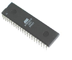
Here is a link for atmega16 datasheet :
datasheet
Total Nine(9) Presentation Are Give in RAR file:
Total Nine(9) Presentation Are Give in RAR file:
List of Presentations:
Course
contents
1- Introduction.
2-Memories in uc.
2-Memories in uc.
3-I/O ports.
4-External and Internal interrupts.
4-External and Internal interrupts.
5-Timers.
6-clock sources and sleep modes.
7-reset sources and watch dog timer.
8-communication using SPI or USART.
9-dealing with analog signals.
here is a link for TutoRial Files (presentations)
http://www.mediafire.com/?6pvhggweygges7i
Programs used in this TuTorial are :
1- avr codevision compiler
1- avr codevision compiler
Saturday, July 14, 2012
Languages Used for Embedded Firmware Development : M.Vasim Khatri ~ Ultimate EC
Introduction
Every digital device that is driven by a CPU core processes some sort of
digital information. Not all of them are digital data. In fact, major portion
of them are some kind of instruction to the CPU. As we all know, they are
patterns of zeros and ones. In groups, those zeros and ones are called as
nibbles (a group of 4), bytes (A group of 8), half word (group of 16) and word
(group of 32). Every microcontroller comes with an inbuilt memory. They store
instruction and data. When their CPU runs, they fetch the code from the memory.
They obtain data either from memory or from external I/O.
The collection of the data
and the code together is called firmware. And the algorithm that the programmer
follows is called a program. The final output of a program is a
binary bit stream that is executed by the CPU. We also call them as hex code.
If someone writes an error free program and generates hex code by
himself/herself, no doubt it will run. But its laborious, time consuming and
prone to error. So as humans always do, less laborious and less problematic
solution of this particular problem has been found out! Computer languages are
brought to work for code generation.
The basic target of any compiler is to generate hex code. Whether it is an
executable file or the collection of the hexadecimal code stored in a file
called “HEX File”. For embedded system, it always comes out in form of
HEX files that is executed by the CPU (Note that few processors like ARM
supports direct JAVA byte code execution). It is later downloaded into target
microcontrollers (we call this process as “burning program to microcontroller”).
Embedded C
C is the immediate advance
language to assembly language for software dehvelopment. Though
microcontrollers provided limited processing power, embedded C developers
managed to integrate most popular functions of ANSI C to embedded C. As
discussed previously, sometimes the IDE developers provide some extensions.
They use keywords, various macros and functions to facilitate programming for
microcontrollers.
Each manufacturers may publish
multiple architectures. And each architecture must have at least one compiler
to support programming. Their architectural difference stops to use one single
compiler for all families. Few specific difference may demand a huge
programming in the compilers framework. So usually manufacturers avoid
publishing a micro controller with very different architecture. The compilers
of manufacturers’ usually doesn’t support other IC manufacturers’
microcontrollers. The major reason is that it is very difficult to develop a
single standard IDE due to large variety of microcontroller family. Here is a
list of few IDE published by popular manufacturers.
|
Publisher
|
IDE
|
|
Renesas
|
Cube Suite Plus
|
|
Texas Instruments
|
IAR Workbench
|
|
National Instruments
|
Lab VIEW
|
|
NXP (a Phillips undertaken
company)
|
LPC Xpresso
|
|
Microchip
|
MPLab SIM
|
|
Atmel
|
AVR Studio
|
|
ARM
|
Keil Microvision
|
JAVA
Most of the embedded IDE doesn’t support java programming. Yet, many JAVA
application runs successfully in many devices. Recently, few IDEs are
adopting JAVA for hex code generation. But this is not the major key to the
success of JAVA in the field of embedded systems. Instead of adapting JAVA as a
program development language, ARM adapted a technique to allow JABA Byte code
to be executed by a single microcontroller. JAVA byte code is the usual output
of a java program. This allowed software professionals to develop JAVA based
software and operating system to run on ARM powered devices. This allowed to
use the existing talents in the IT sectors. This, in turn, pumped up production
of gadgets running with JAVA based systems. Almost 90% of the mobile and
portable devices comes with firmware developed with JAVA.
The impact of adapting JAVA by a microcontroller is a milestone. But efforts
are there to make HEX code generation possible wit JAVA. The pioneer of this
effort is Microchip Corporation. Their IDE MP Lab Sim supports embedded JAVA to
develop a program. Nevertheless, they have to generate hex code for their
microcontrollers.
Wednesday, July 4, 2012
Mobile Phone Jammer
Mobile phone jammer circuit.
It operated at 450 Mhz.
Downlload proteous file here.
jammer by govani
it works*.
It operated at 450 Mhz.
Downlload proteous file here.
jammer by govani
it works*.


